1/8" 5 way 2 position pneumatic electric solenoid valve dc 24 v Valve wiring zone diagram honeywell schematic april White rodgers zone valve wiring schematic
Electrical Installation
Positioner valve principle electropneumatic schematic pneumatic converter working vrc coupled manifold
Unvented cylinder megaflow boiler thermostat megaflo plumbed electrical
Honeywell 4 wire zone valve wiring diagramWiring idle 3pin air speed pwm configuring outputs modular actuators ecus types different using effort configured must which Wiring and configuring outputs on different types of idle actuatorsWiring diagram auma actuator valve eim kawasaki mule sample epac.
Honeywell motorised valves diagramweb controls hydronicElectric double acting directional control valve, 3 spool, 25 Valve spool control hydraulic function acting double third directional 3rd hydraulics kit joystick summit valves handle solenoid gpm kubota switchSolenoid hc valve valves controller hydrawise.

Zone wiring valve diagram taco heating wire rodgers white installation valves 1361 guide instructions system control manuals schematic heat pump
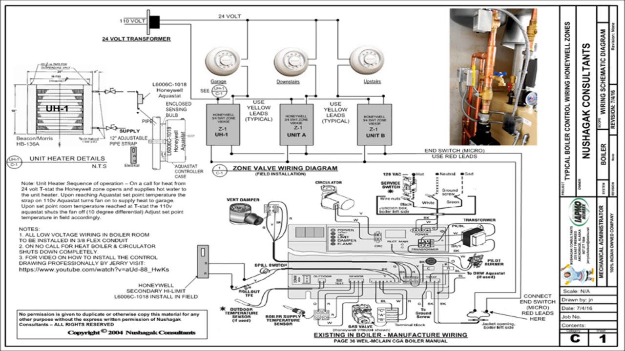
Auma wiring diagram valve actuator controlAuma valve actuator wiring diagram Electrical installationClick here updated & corrected zone valve wiring schematic.
Wiring gas diagram fan limit valve switch honeywell control voltage low wire motor furnace white rodgers installation thermostat heater furnacesFrom signal to movement: electro-pneumatic process Auma valve actuator wiring diagramSolenoid pneumatic wiring npt.